
Stiward Thære SæSteward of the Seas
Compressor and gate setup · November 2026 production preset
Production feed-forward compressor and clean-keyed gate: JP1 A, JP2 B, updated resistance-based starting points and supplied bench results.
On this page
- November 2026 · production setup
- 1. What the board does
- 2. Directions and production starting points
- 3. The map and the starting point
- 4. The controls, one by one
- 5. Setting it up, in order
- 6. Production polish preset
- 7. The two solder jumpers
- 8. If something's wrong
- 9. November production component values
- 10. Reference
- Earlier source documents
November 2026 · production setup
Shipped configuration: JP1 = A, JP2 = B. The compressor sidechain is feed-forward from Audio_In; the PEAK pad stays unbridged. The gate is keyed from the Wall of Ice output through main-board TO_COMP (J23) into compressor J10.
The gate key is pre-distortion and post-Wall-of-Ice, with about 50–60 dB of dynamic range in the supplied bench results. It follows the input rather than the already clipped waveform.
1. What the board does
The Steward follows Aurora Curtain. Its SSI2162 VCA compressor evens the level of the sound after distortion, and its gate quiets the gaps between phrases. Thirteen internal trimmers hold the preset; the panel Comp switch engages the dynamics section.
Shipped configuration: JP1 = A, JP2 = B. The compressor sidechain is feed-forward from Audio_In; the PEAK pad stays unbridged. The gate is keyed from the Wall of Ice output through main-board TO_COMP (J23) into compressor J10.
The gate key is pre-distortion and post-Wall-of-Ice, with about 50–60 dB of dynamic range in the supplied bench results. It follows the input rather than the already clipped waveform.
The detector starts compressing at about 0.4 V peak at TP1. Below that threshold there is no compression; above it, gain reduction grows at about 15 dB per volt until the knee clamp limits it to about 21 dB. Knee1 is inert at polish settings.
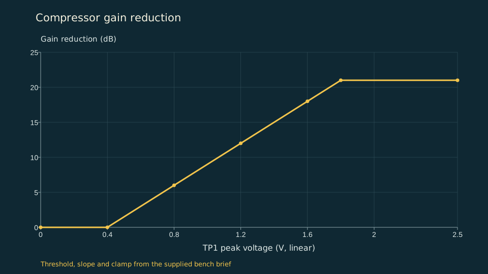
Read the chart data
| TP1 peak (V) | Reduction (dB) |
|---|---|
| 0 | 0 |
| 0.4 | 0 |
| 0.8 | 6 |
| 1.2 | 12 |
| 1.6 | 18 |
| 1.8 | 21 |
| 2.5 | 21 |
2. Directions and production starting points
Resistances are measured from pin 3 to the wiper unless noted. Release trimmers FST_REL1 and SLW_REL1 are measured from pin 1 to the wiper. Use the resistance values below rather than converting older percentage presets.
| Trimmer | Direction / operating point | Production starting point |
|---|---|---|
| ERR1 | 12–20 kΩ operating range with R31 2.2 kΩ | Start 12–15 kΩ; set by ear |
| C_LVL1 | Counterclockwise = maximum depth | Maximum, fully CCW |
| Knee1 | Inert at polish settings | Minimum |
| BLEND1 | Clockwise = wet | 65–75 % wet |
| Out_LVL1 | Unity at about 23 % travel (4.6 kΩ); 35 % gives +3.6 dB make-up | With 1.5 V peak input and Dist at maximum, keep SigOut ≤ 13 V |
| FST_ATT1 | Resistance setting | 8 kΩ |
| SLW_ATT1 | Resistance setting | 40 kΩ |
| FST_REL1 | Measure pin 1 to wiper | 70 kΩ |
| SLW_REL1 | Measure pin 1 to wiper | 60 kΩ |
| G_FAST_ATT1 | Resistance setting | 8 kΩ |
| G_SLOW_REL1 | Clockwise = longer, curved release; fully CCW = instant close | 15–20 kΩ |
| G_LVL1 | Must remain above RV_THR1 | 30 kΩ |
| RV_THR1 | Bottom 2 kΩ is a dead band; keep below G_LVL1 | 15 kΩ; at least 2 kΩ from pin 3 for the floor to engage |
3. The map and the starting point
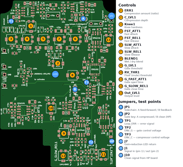
The component-side map locates the trimmers, jumpers, test points and connectors. It is the earlier board illustration; the November production table above supplies the current settings.
4. The controls, one by one
Compressor sensitivity, depth and blend
ERR1 sets sidechain sensitivity over the working 12–20 kΩ range with R31 = 2.2 kΩ. C_LVL1 reaches maximum depth fully counterclockwise. Leave Knee1 at minimum for the polish starting point: it is inert at those settings. BLEND1 turns clockwise toward wet; start at 65–75 % wet to retain some uncompressed attack.
Attack and release
Start FST_ATT1 at 8 kΩ, SLW_ATT1 at 40 kΩ, FST_REL1 at 70 kΩ and SLW_REL1 at 60 kΩ. Measure both release trimmers from pin 1 to the wiper. The fast and slow detector paths share the work of catching attacks and riding the phrase.
Output level
Out_LVL1 unity is about 23 % travel, or 4.6 kΩ. The older 35 % setting adds about +3.6 dB of make-up. Set it with 1.5 V peak input and Dist at maximum so SigOut stays at or below 13 V.
Gate thresholds and timing
The gate closes in two stages: detector hold, about 0.3 s with R39 = 100 kΩ, followed by the curved G_SLOW_REL1 ramp. The trimmer sets the ramp, not the whole release time. Clockwise makes that ramp longer; fully counterclockwise gives instant closure after the detector hold.
With RV_THR1 above its hysteresis band, the floor comparator gives a fully closed plateau at TP2 around +3.7 V, about 85 dB of attenuation. Below the band the gate only partially closes, with TP2 around +1.4 V. Keep RV_THR1 below G_LVL1 and above the bottom 2 kΩ dead band.
Gate opening is immediate with C56 = 220 nF; the previous approximately 0.3 s fade-in is removed.
5. Setting it up, in order
- Disconnect power before opening or changing jumpers. Set JP1 = A and JP2 = B, with PEAK unbridged and the clean key connected through J23 → J10.
- Set the resistance-based starting points in the table. Begin with ERR1 at 12–15 kΩ, C_LVL1 at maximum fully CCW, Knee1 minimum and BLEND1 at 65–75 % wet.
- Set ERR1 by ear with the intended source. Check TP1 against the approximately 0.4 V peak detector threshold and listen to accents and quiet notes.
- Check the gate with sustained notes and pauses. Start G_LVL1 at 30 kΩ, RV_THR1 at 15 kΩ and G_SLOW_REL1 at 15–20 kΩ; keep the floor below the working threshold.
- Set Out_LVL1 with 1.5 V peak at the input and Dist at maximum, keeping SigOut at or below 13 V. Its unity reference is about 23 % travel, or 4.6 kΩ; match bypass and engaged levels for the intended preset.
6. Production polish preset
The production starting preset is ERR1 12–15 kΩ, C_LVL1 maximum fully CCW, Knee1 minimum and BLEND1 65–75 % wet. Use the timing and gate values in §2, then set ERR1 by ear and Out_LVL1 against the output limit.
The earlier percentage-based feedback presets are superseded for this feed-forward production setup.
7. The two solder jumpers
Shipped configuration: JP1 = A, JP2 = B. The compressor sidechain is feed-forward from Audio_In; the PEAK pad stays unbridged. The gate is keyed from the Wall of Ice output through main-board TO_COMP (J23) into compressor J10.
The gate key is pre-distortion and post-Wall-of-Ice, with about 50–60 dB of dynamic range in the supplied bench results. It follows the input rather than the already clipped waveform.
Confirm jumper isolation with power disconnected. Do not bridge all three pads: selecting another position requires opening the previous connection first. The production setup uses A for the compressor and B for the gate; the gate needs the J23 → J10 key connection.
8. If something's wrong
| Symptom | Check |
|---|---|
| No compression | Check JP1 A, PEAK unbridged, TP1 above about 0.4 V peak, ERR1 in its 12–20 kΩ working range and C_LVL1 fully CCW for maximum depth. |
| Too much make-up level | Check Out_LVL1: unity is about 23 %, not 35 %. Keep SigOut ≤ 13 V in the stated maximum-drive check. |
| Gate only partly closes | Check RV_THR1 above its bottom 2 kΩ dead band and below G_LVL1. The fully closed TP2 plateau is around +3.7 V; a partial close is around +1.4 V. |
| Gate closes too slowly | Allow for the 0.3 s detector hold plus the G_SLOW_REL1 ramp. Counterclockwise shortens that ramp. |
| Gate does not follow quiet playing | Check JP2 B and the Wall of Ice key connection J23 → J10, then adjust thresholds with the intended instrument. |
9. November production component values
| Reference | Production value | Purpose / reported result |
|---|---|---|
| R31 | 2.2 kΩ | Feed-forward sidechain pad |
| R48 | 2.2 kΩ | Sidechain summing gain |
| R29, R95 | 100 kΩ each | Y-node mixing; prevents audio leaking onto the control voltage |
| R33 | 1 MΩ | C2 coupling corner 0.71 Hz; input pad loss about −0.11 dB |
| R39 | 100 kΩ | Detector hold about 0.3 s |
| C56 | 220 nF | Floor comparator smoothing; immediate gate opening |
10. Reference
All compressor-board coupling corners are below 2 Hz after the R33 change. The C2 / R33 input corner is about 0.71 Hz, with approximately −0.11 dB input pad loss.
Technical design and detector curve · Player’s guide · Production drive reference
Earlier source documents
The unchanged Rev 2 Word references below contain older component values and feedback presets. The November production settings on this page take precedence.