
Steward of the Seas technical design
Technical design · November 2026 production update
Production compressor and gate reference: feed-forward Audio_In sidechain, clean Wall of Ice gate key, 0.4 V TP1 threshold and approximately 21 dB maximum reduction.
On this page
- November 2026 · production technical reference
- 1. Overview
- 2. Audio path
- 3. Compressor sidechain
- 4. Static response
- 5. Dynamic response
- 6. Gate / expander
- 7. Controls reference and rotation sense
- 8. Test points and expected readings
- 9. Measurement scope
- 10. Connections and calibration checks
- 11. Production component values
- 12. Checking the preset
- 13. Plot and calibration scope
- Appendix A — Related main-board changes made in the same sessions
- Earlier source documents
November 2026 · production technical reference
Shipped configuration: JP1 = A, JP2 = B. The compressor sidechain is feed-forward from Audio_In; the PEAK pad stays unbridged. The gate is keyed from the Wall of Ice output through main-board TO_COMP (J23) into compressor J10.
The gate key is pre-distortion and post-Wall-of-Ice, with about 50–60 dB of dynamic range in the supplied bench results. It follows the input rather than the already clipped waveform.
1. Overview
The SSI2162 dynamics board follows Aurora Curtain. One VCA controls compression; the phase-correct blend combines dry and compressed audio before the gate. Thirteen trimmers provide the internal preset.
Shipped configuration: JP1 = A, JP2 = B. The compressor sidechain is feed-forward from Audio_In; the PEAK pad stays unbridged. The gate is keyed from the Wall of Ice output through main-board TO_COMP (J23) into compressor J10.
The gate key is pre-distortion and post-Wall-of-Ice, with about 50–60 dB of dynamic range in the supplied bench results. It follows the input rather than the already clipped waveform.
The detector starts compressing at about 0.4 V peak at TP1. Below that threshold there is no compression; above it, gain reduction grows at about 15 dB per volt until the knee clamp limits it to about 21 dB. Knee1 is inert at polish settings.
2. Audio path
The input buffer provides Audio_In to the dry blend and the feed-forward sidechain. The compressed signal is phase-corrected for parallel blending, then the gate controls the result before the output stage.
R33 is now 1 MΩ. The C2 input coupling corner is about 0.71 Hz, with approximately −0.11 dB pad loss. Every coupling corner on the compressor board is below 2 Hz.
Out_LVL1 unity is approximately 23 % travel (4.6 kΩ); 35 % is about +3.6 dB of make-up gain. With 1.5 V peak input and Dist at maximum, adjust it so SigOut stays ≤ 13 V.
3. Compressor sidechain
Source and gain
Shipped configuration: JP1 = A, JP2 = B. The compressor sidechain is feed-forward from Audio_In; the PEAK pad stays unbridged. The gate is keyed from the Wall of Ice output through main-board TO_COMP (J23) into compressor J10.
The gate key is pre-distortion and post-Wall-of-Ice, with about 50–60 dB of dynamic range in the supplied bench results. It follows the input rather than the already clipped waveform.
R31 = 2.2 kΩ provides the feed-forward pad, and R48 = 2.2 kΩ sets the revised summing gain. The reported sidechain gain is ERR1 divided by 8.4 kΩ, net of R48. ERR1 operates over about 12–20 kΩ; the starting range is 12–15 kΩ.
Detector and envelope
The detector starts compressing at about 0.4 V peak at TP1. Below that threshold there is no compression; above it, gain reduction grows at about 15 dB per volt until the knee clamp limits it to about 21 dB. Knee1 is inert at polish settings.
R29 and R95 are now 100 kΩ each at the Y-node, preventing audio from leaking onto the control voltage. C_LVL1 reaches maximum depth fully counterclockwise. Knee1 remains at minimum for polish.
4. Static response
The detector starts compressing at about 0.4 V peak at TP1. Below that threshold there is no compression; above it, gain reduction grows at about 15 dB per volt until the knee clamp limits it to about 21 dB. Knee1 is inert at polish settings.
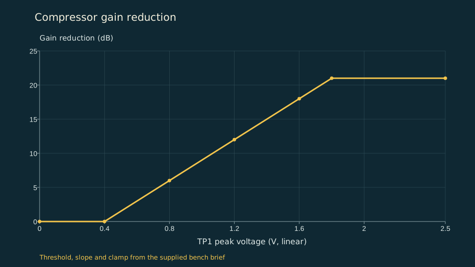
Read the chart data
| TP1 peak (V) | Reduction (dB) |
|---|---|
| 0 | 0 |
| 0.4 | 0 |
| 0.8 | 6 |
| 1.2 | 12 |
| 1.6 | 18 |
| 1.8 | 21 |
| 2.5 | 21 |
| TP1 peak | Gain reduction |
|---|---|
| 0–0.4 V | 0 dB |
| 0.8 V | 6 dB |
| 1.2 V | 12 dB |
| 1.6 V | 18 dB |
| 1.8 V and above | About 21 dB, knee clamp |
5. Dynamic response
The fast detector catches attacks while the slow detector follows the phrase. The production starts are FST_ATT1 8 kΩ, SLW_ATT1 40 kΩ, FST_REL1 70 kΩ and SLW_REL1 60 kΩ. Both release values are measured from pin 1 to the wiper; the attack values use pin 3 to the wiper.
These resistance settings replace the earlier feedback-mode percentage presets. Set sensitivity and blend with the intended source; the current brief does not provide new measured compressor attack or release times.
6. Gate / expander
The gate closes in two stages: detector hold, about 0.3 s with R39 = 100 kΩ, followed by the curved G_SLOW_REL1 ramp. The trimmer sets the ramp, not the whole release time. Clockwise makes that ramp longer; fully counterclockwise gives instant closure after the detector hold.
With RV_THR1 above its hysteresis band, the floor comparator gives a fully closed plateau at TP2 around +3.7 V, about 85 dB of attenuation. Below the band the gate only partially closes, with TP2 around +1.4 V. Keep RV_THR1 below G_LVL1 and above the bottom 2 kΩ dead band.
Gate opening is immediate with C56 = 220 nF; the previous approximately 0.3 s fade-in is removed.
Start G_FAST_ATT1 at 8 kΩ, G_SLOW_REL1 at 15–20 kΩ, G_LVL1 at 30 kΩ and RV_THR1 at 15 kΩ. The key has approximately 50–60 dB of dynamic range because it is taken before distortion.
7. Controls reference and rotation sense
Resistances are measured from pin 3 to the wiper unless noted. Release trimmers FST_REL1 and SLW_REL1 are measured from pin 1 to the wiper. Use the resistance values below rather than converting older percentage presets.
| Trimmer | Direction / operating point | Production starting point |
|---|---|---|
| ERR1 | 12–20 kΩ operating range with R31 2.2 kΩ | Start 12–15 kΩ; set by ear |
| C_LVL1 | Counterclockwise = maximum depth | Maximum, fully CCW |
| Knee1 | Inert at polish settings | Minimum |
| BLEND1 | Clockwise = wet | 65–75 % wet |
| Out_LVL1 | Unity at about 23 % travel (4.6 kΩ); 35 % gives +3.6 dB make-up | With 1.5 V peak input and Dist at maximum, keep SigOut ≤ 13 V |
| FST_ATT1 | Resistance setting | 8 kΩ |
| SLW_ATT1 | Resistance setting | 40 kΩ |
| FST_REL1 | Measure pin 1 to wiper | 70 kΩ |
| SLW_REL1 | Measure pin 1 to wiper | 60 kΩ |
| G_FAST_ATT1 | Resistance setting | 8 kΩ |
| G_SLOW_REL1 | Clockwise = longer, curved release; fully CCW = instant close | 15–20 kΩ |
| G_LVL1 | Must remain above RV_THR1 | 30 kΩ |
| RV_THR1 | Bottom 2 kΩ is a dead band; keep below G_LVL1 | 15 kΩ; at least 2 kΩ from pin 3 for the floor to engage |
8. Test points and expected readings
| Test point | Current reported behaviour |
|---|---|
| TP1 | Detector threshold about 0.4 V peak; reduction grows about 15 dB/V above it. |
| TP2 | Fully closed floor plateau about +3.7 V, approximately 85 dB attenuation; partial close around +1.4 V. |
| TP3 | Compressor envelope monitor. The brief does not give a replacement absolute voltage calibration for this node. |
| SigOut | Keep ≤ 13 V with 1.5 V peak input and Dist at maximum when setting Out_LVL1. |
9. Measurement scope
The November 1 brief reports October–November prototype bench work with a Digilent Analog Discovery 3 and a scope. Its production values supersede the older design figures. The compressor curve here is constructed only from the supplied threshold, slope and clamp.
The drive sweep uses 20 mV excitation, Dist at 12.2 kΩ, filters open and a 10× output probe. The 20 dB probe correction is already included in the supplied gain values.
10. Connections and calibration checks
Use locking connectors on the ±15 V rail leads and check both rails before calibration. With power disconnected, verify that each three-pad jumper selects only its intended source and does not short the alternatives together.
11. Production component values
| Reference | Production value | Purpose / reported result |
|---|---|---|
| R31 | 2.2 kΩ | Feed-forward sidechain pad |
| R48 | 2.2 kΩ | Sidechain summing gain |
| R29, R95 | 100 kΩ each | Y-node mixing; prevents audio leaking onto the control voltage |
| R33 | 1 MΩ | C2 coupling corner 0.71 Hz; input pad loss about −0.11 dB |
| R39 | 100 kΩ | Detector hold about 0.3 s |
| C56 | 220 nF | Floor comparator smoothing; immediate gate opening |
12. Checking the preset
Match the output and gate thresholds with the intended instrument, then test soft notes, hard accents and sustained decays. The production resistance settings are a starting preset; they do not guarantee identical behaviour with every source.
13. Plot and calibration scope
The published detector plot uses the supplied piecewise-linear description: no reduction through 0.4 V peak, approximately 15 dB/V above threshold, capped near 21 dB. It is not a new measurement of compression ratio for every frequency, blend or timing setting.
Older Rev 2 curves and feedback-mode measurements remain in the dated source documents. They should not be reused as the production feed-forward calibration.
Appendix A — Related main-board changes made in the same sessions
The production drive has three R–C voicing legs, R54 = 220 kΩ, R53 = 470 Ω and an output presence shelf matched to Aurora Curtain’s closed corner near 3 kHz. Its ladder bends at ±3.65 V and clamps at ±4.55 V.
See the drive response data and production component tables.
Earlier source documents
The unchanged source documents below preserve the earlier Rev 2 record. Their parts, presets and model curves are superseded by the production values on this page.